


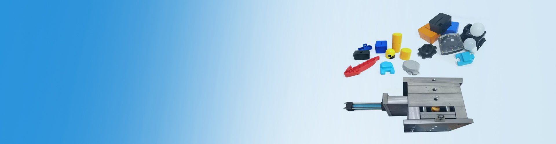
Plastic Injection Tooling
Injection molding is a fundamental process for plastic parts fabrication. The operation needs an injection molding equipment and different types of plastic injection tooling.
Also known as injection mold, plastic injection tooling is a device used in carrying out injection molding procedures. It comprises of a cavity and core that aid in forming desired plastic parts.
Injection Tooling Design Considerations
The following are the most essential factors to consider during designing of plastic injection mold:

Necessary in both the cavity and core for effortless discharge of final product.

Water flows across the openings bored in both cavity and core plates to lower the cycle time.

Helps in eliminating gases trapped between the cavity and core since excess gaps might lead to flash defects.

It may reduce in volume when cooling. Hence, important to design the injection tool to accommodate this shrinkage.

The space between the face of the core back plate and that of ejector plate needs to maintain dimension in the core.

Gate placement should ensure component filling from thicker segment to thinner segment.
Plastic Injection Mold Alignment
The cavity and core of plastic mold are aligned during each injection molding cycle to ensure quality production. This positioning is made possible by guide bush and guide pillar.
Four guide bushes and guide pillars are normally utilized. Three of these pillars have equal diameter, with one having different diameter, forcing the plates into one configuration.
The register ring features transmission fit having the plastic injection molding equipment pattern and interference fit within upper plate. It is instrumental in the alignment of the upper plate of the mold and the machine pattern.

Injection Mold Material Selection


Making the right choice of material for your injection tooling is important as it influences the durability and the quality of production. Your choice of the tooling material should depend on part compatibility, plastic to be molded and your budget.
Here are some of the commonly used materials in plastic injection tooling:
Steel – The most commonly used material in making of injection tooling. Steel has high tensile strength, durability and resistance to extreme temperatures. It is available in different grades and you can choose the type of steel based on the desired performance.
Steel can also be mixed with other metals to make injection molds. Steel injection molds may also need to be coated with Nickel for use in highly corrosive environments.
Aluminum – Aluminium is a cheaper option as compared to steel. However, they are less durable. They offer good conductivity to heat, are lightweight and require frequent maintenance.
Copper Alloys – Copper alloys such as Beryllium-Copper alloy can be used to make injection molds with great thermal conductivity and high resistance to corrosion. They provide fast cooling to the molten plastic and are the most expensive option.
Plastic Injection Tooling Machining


Standard Machining
Standard machining of plastic injection molds conventionally entails utilizing lathe machines, milling equipment, and drill press machines. Still, because to innovations in technology, CNC machining has taken over as the primary technique for fabricating more precise and detailed plastic injection tools. This is possible whilst still utilizing standard machining techniques.
Latest automatic CNC machines considerably simplify the process of designing and constructing plastic injection tooling.
The mechanical details of the tooling are assigned with the aid of CAD software, and that data is subsequently converted into production instructions using CAM software. The individual instructions necessary to operate each machinery utilized in the mold construction operation are then generated from these commands by post processor program. The system then feeds the final commands into the CNC machinery that completes the plastic injection mold fabrication process.
Electrical Discharge Machining
Injection mold construction is quickly adopting electrical discharge machining as the preferred fabrication technique. Using copper or graphite electrode, the EDM method makes it easier to construct the mold shape you want. The electrode is fitted within EDM equipment and setup atop the mold material, which is fully immersed in a dielectric medium.
The electrical discharge from the machine will react with the electrode to erode the unwanted parts of the workpiece, leaving the desired injection mold structure and shape. Although it is slower, EDM may construct plastic injection tooling designs that are considered impractical for normal CNC machining.
Additionally, pre-hardened tooling may be molded through the EDM technique, excluding the demand of further heat-treatment. Sometimes, there is no need for smoothening the injection mold cavity as EDM produces parts with polished surfaces.
Corrosion Protection of Plastic Injection Mold
Stainless steels or nickel plating may be necessary to stop plastic mold corrosion when working in a high moisture environment. There is high chance of corrosion if using cold plastic injection tooling where condensation and eventual oxidation might happen. Using materials that might release a gas which is intrusive to majority of steel types can also cause corrosion.
Nickel plating is a common technique of making the plastic injection mold material corrosion resistant. It is the ideal method to apply in cases requiring corrosion protection surpassing preventative spraying or for long-term injection tooling storage.
Electroless nickel plating guarantees exceptional shielding and is comparatively less costly in comparison to chrome or additional corrosion protection methods. Moreover, the technique ensures greater mechanical features like hardness, abrasion resistance, toughness, and higher thermal conductivity compared to stainless steels.
Why Plastic Injection Tooling is Important

Plastic injection molds allow the molten plastic to be manufactured in different shapes and sizes to meet the needs of the user.

They can be used repeatedly hence provide a cheap solution in the manufacture of plastics. The molds are not disposed of once used; hence the same mold ca n be used in the manufacture of a huge volume of plastics.

Lead time is minimized as the injection molds can be used in the mass production of plastics at a time. This ensures that the demands of the user are not only met as fast as possible but also executed efficiently.

Plastic injection tooling are used to produce plastics that meet the standards of the manufacturer. They ensure that the shapes and size of the plastic are produced accurate.
Types of Plastic Injection Tooling
There exist several plastic injection molds types depending on a number of features. Selecting the most suitable type is critical since the mold will influence the manufacturing speed, quality of final plastic part, and general costs.
The various types of injection tooling are categorized into four main groups based on the following attributes:
Number of Mold Plate
Plastic injection tooling can also be classified based on the number of mold plates they contain. This group comprises of three major injection mold types including:
Two-Plate Injection Mold
This is the commonest type in this group due to its low tooling expenses. Two-plate injection tooling features a single parting line along where the cavity and core plates meet. Its parting line, runner and gate must align as well. Two-plate injection mold work well with any kind of runner system though it is best matched with single cavity tooling.
Three-Plate Injection Mold
The incorporation of stripper plate gives this mold two parting lines. The extra plate is installed in the middle of the core and cavity plates, inevitably isolating the runner mechanism from the formed part. Because of this, three-plate injection tooling enables faster plastic fabrication process since runner system recycling or manual isolation is not necessary.
Nevertheless, the extra plate raises the general tooling cost since the cutting should be accurate to conform to the other 2 plates. Three-plate molds are only suitable for cold runner mechanisms as the stripper plate aids in detaching the runners.
Stack Injection Mold
Stacked plastic tooling features several parallel mold plates to ensure more efficient injection molding process. It needs lower clamp tonnage in every molding cycle.
The investment capital of this type of plastic injection tooling is very high since it requires longer time to construct. Even so, the reduced clamp tonnage need lessens the operation expenses. Furthermore, there are stack injection mold designs can process various plastic materials at the same time.
Number of Cavities
These group comprise of three types of plastic injection tooling with respect to the number of items then can form in each molding cycle:
Single Cavity Mold
Single cavity injection tooling creates one plastic part in every injection cycle. Despite being a slow fabrication mold type, its machining costs are lesser in comparison to other choices. This makes low-volume fabrication using the mold more affordable. Moreover, this injection mold type also facilitates better management of the molding procedure.
Multi Cavity Mold
Multiple cavity injection mold design enables creation of several identical plastic part in a single molding cycle. The investment cost for this type of injection tooling is usually greater compared to single cavity version.
Even so, multi-cavity injection tooling is more appropriate for mass productions since it produces numerous parts at a go. This leads to faster manufacturing and lowered production costs.
Family Injection Mold
Family injection tooling also features multiple cavities similar to multi-cavity molds. Nonetheless, they are perfect for producing many non-identical parts in every injection molding cycle.
Though expensive, family injection mold lowers the general fabrication costs since it enables molding of several different plastic parts. Additionally, it saves exceptionally on operation expenses and time. Yet, these plastic injection tooling types are solely appropriate for parts of similar color and material.
Feeding System
The feeding or runner system refers to a sequence of channels, constituting runners, sprues, and gates. These channels route the melted plastic stock from the feeding nozzle to the preferred cavity parts. The injection molds types in this group include:
Hot Runner Injection Tooling
The hot runner mold features runners that are heated either externally or internally using rods or coils. These runners remain permanent inside a static manifold plate that encloses them, preventing their ejection with the plastic part.
They produce clean injection molded parts having no additional plastic residue. This lessens waste generation and does away with any extra operations to recycle or remove the runners.
Moreover, post-processing or regrinding is often not necessary, making the plastic injection molding procedure much faster. If blended with multi-cavity tooling, hot runner injection mold enables mass fabrication of fine and complex shapes.
However, setting up, heating and maintaining the system is normally very expensive, and needs skilled personnel to oversee the molding operation. Also, cleaning the system may be a challenge due to the hidden nature of the runners.
Cold Runner Injection Tooling
Here, the runners are unheated and exposed. A new runner mechanism is necessary with each plastic injection molding cycle. Dependent on the mold plate type employed, the runner system and molded item may be separated or fused upon ejection.
Cold runner injection tooling facilitates quicker and simpler material and color alteration. They can handle a broad material variety and ensure easier cleaning and maintenance. Nonetheless, this plastic injection mold type generates a lot of scrap for every cycle since they are rarely reused.
Insulated Runner Molds
These types of plastic injection tooling resemble conventional cold runner molds. But they feature cartridge heaters or additional types of heating to form an encircling layer of melted plastic. This creates insulated mold with same effects as hot runner injection tooling.
Insulated runner injection mold is often the preferred choice since it does not need temperature controller, which makes it more affordable than hot runners. Moreover, it allows for quicker and faster changeover of colors and materials.
Nonetheless, these injection mold types are not compatible with all sorts of materials. The tooling is not appropriate for challenging engineering-grade plastics.
Unscrewing Injection Mold
These are the most ideal plastic tooling for forming threaded plastic parts. They represent automated injection molds that have drive mechanism consisting of either:
- Hydraulic motors
- Electric motors
- Rack and pinion
This distinctive injection tooling spins the drive mechanism to produce threaded parts like bolts and nuts, bottle caps, and automotive parts. Removing these parts employing ordinary knock-off technique depend on draft angle is usually challenging.
Thus, unscrewing plastic injection tooling helps do the removal minus causing any damage on the threads. It functions at elevated speed, ensuring bulk manufacturing and lowered cycle times. Typically, the mold works well with undercut injection molding as it permits discharge of intricate parts without damage.
Plastic Injection Mold Design
The core and cavity are the two primary components of plastic injection tooling. The core represents the male part of injection mold that develops the internal molding shape. Conversely, the cavity refers to the female segment that creates the external molding shape.
Plastic injection tooling design and structure normally differ depending on the type of tooling, material properties, and required final products. Nevertheless, the basic injection mold structure stays the same with the following integral components:
- Register Ring – Helps in aligning the injection molding machinery screws with the plastic injection tooling.
- Sprue Bushing – The molten material is injected into the mold via this part. It features a taper aperture of 3-5 degrees.
- Top Plate – Serves in clamping the upper mold half to the movable half of the plastic injection molding machine.
- Cavity Plate – Forms the chamber that will get loaded with the melted plastic resin necessary to fabricate the plastic part.
- Core Plate – The part of injection mold protrudes into the cavity to shape the hollow sections of the plastic part.
- Sprue Puller Bushing – This is the part that holds the sprue puller pin.
- Sprue Puller Pin – Draws the sprue out of the sprue bush.
- Core Back Plate – Supports the core insert in position and serves as a “stiffener.
- Guide Bushing and Guide Pillar – These are the components that align the mobile and fixed halves of the plastic injection mold in every cycle.
- Ejector guide Bush and Guide Pillar – These injection mold parts are instrumental in the injector assembly alignment to prevent destruction of the ejector pins. Normally, the guide pillar has greater hardness in comparison to the guide bush.
- Ejector Plate – This the component that carries the ejector pins.
- Ejector Back Plate – Serves to prohibit the detachment of the ejector pins.
- Heel Blocks – Facilitates ejection of end product from the core by providing a space for ejector system.
- Bottom Plate – Secures the base half of the injection tooling with the anchored half of the plastic injection molding equipment.
- Centering Bush – Helps in aligning the core back plate and the base plate.
- Rest button – Reinforce the ejection system and lessens the contact area between the base plate and ejection assembly. The rest button is especially instrumental during cleaning of injection molding equipment, which is critical in guaranteeing “unmarked” end products.
Tiny foreign particulates adhering on the base plate might make the ejection pins to protrude of the core. This can lead to ejection pin spots on the created plastic part.
Gate
There are two primary gate systems used in plastic injection molds including automatically and manually trimmed gates. Here are various gate systems and where they are employed:
- Sprue Gate – Utilized for production of large plastic injection molded parts, does not require runner and the gate trace is evident in the formed part.
- Winkle Gate – Often employed in the fabrication of plastic electronic products where the gate circulates the molten material below the core side.
- Edge Gate – Highly appropriate for rectangular and square plastic parts.
- Submarine Gate – Employed if automatic de-gating is necessary to lower cycle time.
- Diaphragm Gate – Perfect for hollow, cylindrical injection molded products.
- Tab Gate – The best choice for concrete, thick plastic parts.
- Ring Gate – Ideal when fabricating cylindrical parts to avoid weld line flaws.
- Pin Gate (Reverse Taper Sprue Gate) – Typically applied in three plate plastic injection tooling.
Ejection system
The component that removes the formed plastic part from the injection mold. There are various ejection systems that can be employed including:
- Sleeve Ejection – Sleeve ejection system is ideal for and restricted to cylindrical core, in which the core is secured within the base plate. The system is made up of a sleeve which glides above the core and discharges the formed product. It does not create ejection marks on the final plastic component.
- Core Rotation – This type ejection system for plastic injection molds automatically discharges the part through rotation of the core insert. It is employed for internal threaded plastic parts.
- Stripper Plate Ejection – This ejection system is appropriate for plastic injection molded parts with broader areas. It requires extra stripper plate in the middle of the cavity and core plates. To prevent flash, a space is kept between the core and cavity plate and the stripper plate touches the cavity plate throughout. Stripper ejection plate does not leave notable ejection marks.
- Air Ejection – In this system, compressed air helps in actuating the ejection pin installed inside the core. An attached spring assists in retracting the ejection pin.
- Blade Ejection – Blade ejection system is best choice for products with slim, rectangular cross-sectional surface. Cylindrical pins are tooled to form rectangular cross sections or rectangular blades fitted into cylindrical pins to form suitable ejection length. Introducing a counter bore within the ejection plates facilitates easy integration of ejection pin head.
- Pin Ejection – Cylindrical pins play an integral role in ejecting the finished part. For rectangular and square products, there has to be at least four pins installed at the 4 corners. Similarly, three equidistant pins placed 120 degrees apart are necessary for cylindrical plastic parts.
The number of pins necessary might differ depending on the plastic part size, profile, and ejection area. Pin ejection system leaves noticeable ejection spots on the final product.
More Resources:
- Injection Molding Plastic – Source: Science Direct
- Injection Molding process – Source: Wikipedia