


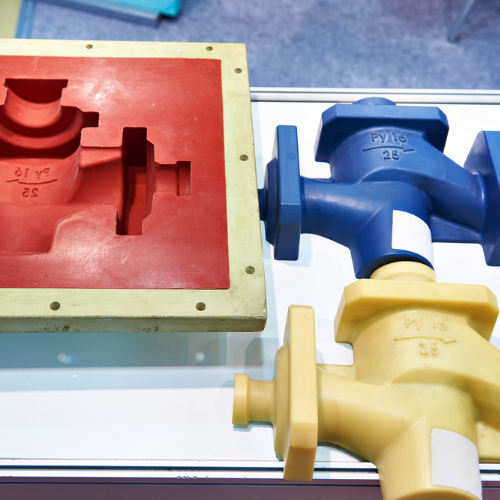
Plastic Injection Molding
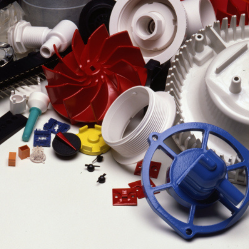
Injection molding is the among the most preferred plastic parts fabrication techniques. It facilitates manufacturing of a broad range of products that differ significantly in their application, size and intricacy.
The process utilizes raw plastic material, a mold, and an injection molding machine. The machine melts the plastic and then introduces it into the injection mold, in which it experiences cooling and curing into the finished part.
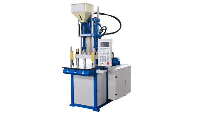
Vertical Injection Molding
In this type of plastic injection molding technique, the mold opens and shuts on a vertical axis. Vertical injection molding machine has the mold positioned at the top, enabling mold cavities filling through gravity. This leads to a constant molten plastic flow and faster filling time. Gravity-aided filling also lessens the clamping force and pressure needed.
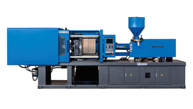
Horizontal Injection Molding
The mold moves horizontally during opening and closing. There is need to apply sufficient pressure to facilitate filling of the mold cavities since gravity does not impact the molten plastic flow.
Nevertheless, the horizontal configuration allows the molded part to fall off upon separation of the injection mold halves. Therefore, it does not require manual extraction of the plastic part on ejection.
Horizontal plastic injection molding also features molds with additional cavities, enabling more plastic parts fabrication per run. This makes it a perfect choice for injection molding applications that need higher parts volume.
Insert Injection Molding
Insert molding process features several similar steps as standard plastic injection molding. The primary difference is that the method involves addition of inserts as extra procedure. Incorporation of sturdy insert attachment points help in improving the overall strength of the plastic part.
Nonetheless, the injection tooling employed in insert molding requires a protective mechanism to inhibit high temperature and pressure from destroying the inserts. You should make sure that the insert position does not shift during the process of injection molding. It is for this reason that secure installation is necessary to prevent any displacement.
Overmolding
Overmolding fabricating a plastic part by merging differing materials. It is commonly employed to construct plastic parts having a rubber handle.
The first overmolding process step is injection, followed by cooling and curing of the first layer. You then complete the operation by adding the second layer and allow it to cure to form the end product.
Dependent on your injection molding part design, you can incorporate over two layers. The base features a hard plastic, whilst the external layer is usually made using a narrow, rubber-like elastomer. Apply plastic overmolding process to enhance the appearance and performance of the product.
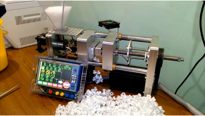
Micro Injection Molding
Micro injection molding is ideal for fabrication of plastic products requiring 0.1 to 1 gram shot weight and low shrink tolerance spanning from 10 to 100 microns. The process enables manufacturing of intricate miniature plastic parts with utmost precision and accuracy.
Micro injection molding fundamentals are the same as traditional injection molding process. The common applications of micro injection molding involve making of plastic parts for use in automotive, medical, optical, electronic, and pharmaceutical sectors.
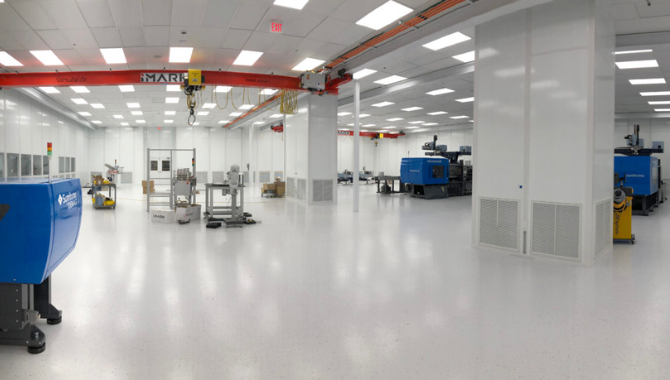
Cleanroom injection Molding
Cleanroom molding takes place inside a unique room that minimizes the chance of plastic part contamination. The special environment maintains the sterility of the part during the injection molding process.
The cleanroom design regulates the environmental condition of the molding operation, including temperature, humidity, and pressure. Military, medical, biotech, and pharmaceutical industries can apply cleanroom injection molding to manufacture special plastic parts.
Plastic Injection Molding Machine Specification
Injection molded plastic parts can differ considerably in size and thus need specific equipment setting for their production. Therefore, you should pay attention to these specifications of injection molding machine when shopping for one:
- Clamp force
- Clamp stroke
- Platen size
- Minimum mold thickness
- Shot capacity

Plastic Injection Molding Vs 3D Printing


3D printing entails depositing materials in a layer-by-layer manner with the aid of 3D prototype of the wanted plastic part. On the other hand, plastic injection molding involves feeding molten polymer material into a tooling cavity subjected to high pressure, constructing a part instantly.
Below are the differences between plastic injection molding vs 3D printing:
| Parameter | Injection Molding | 3D printing |
| Materials | Thermoplastics, certain specialty materials in advanced machinery | Thermosets, thermoplastics, ceramic, impregnated materials, metals. |
| Cost | High capital requirement, low cost per plastic part | Medium to high capital investment, medium to high for every unit |
| Production volume | 1000s-10,000s parts | 1-10 parts |
| Lead times | Slow inceptive lead times for injection mold machining, fast fabrication lead times | Fast general lead times |
| Part size | Highly changeable (Possible to produce both very large and tiny parts) | Limited by build area, part size typically cannot be go beyond a cubic meter |
| Waste | Minimal to no waste, and residue can be recycled | High waste yield |
| Design changes | Difficult, alterations are slow | Very easy, swift changes are practical |
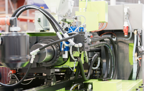
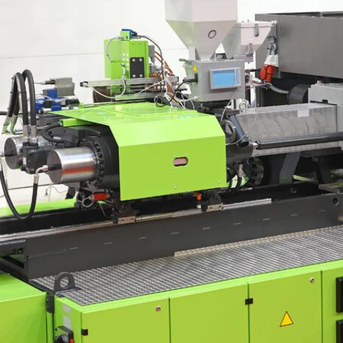
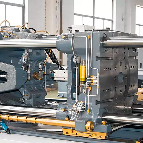
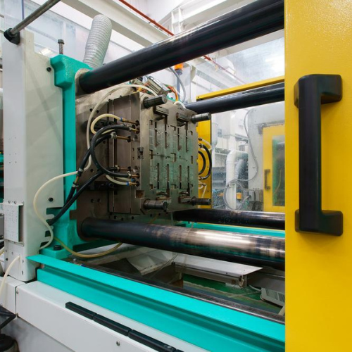
Plastic Injection Molding Machine Parts

There are two main parts of plastic injection molding machine including:
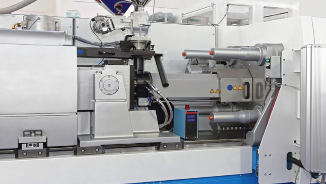
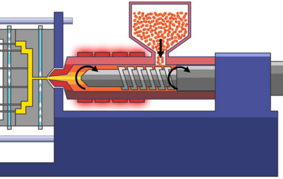
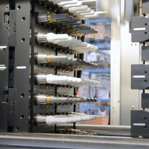
Injection Unit
This the injection molding machine component that delivers the molten plastic into the tooling cavity. The injection unit constitutes three key elements consisting of:
- Hopper: The contain where you place the raw material for plastic injection molding.
- Heated barrel: Exterior injection molding equipment housing that holds the granular/pellet materials and reciprocating screw. The barrel is encased with numerous heater bands that supply the heat for melting the plastic granules/pellets. It also features a heated nozzle at the tip that serves as an outlet for releasing molten plastic into mold cavity.
- Reciprocating screw: Refers to corkscrew element with variable pitch that transfers the materials up the barrel, increasing pressure, whilst concurrently melting the raw material more.
Clamping Unit
This is the part that grip the two injection mold parts together securely during the injection and cooling phase. The clamping unit comprises of three fundamental elements including:
- Mold: The component featuring injection mold cavity and extra supplementary elements like vents, cooling channels, runner channels, ejectors pins among others.
- Immobile and Movable platen: The immobile platen is the component on which the mold cavity is secured. The movable platen supports the mold core and exerts pressure to ensure an airtight part cavity and releases the core after curing of finished part.
- Clamping cylinder and clamping motor drive: Thrust the movable platen down a tie rod set towards the immobile platen. The clamping motor drive power dictates the clamping force and tonnage of the injection molding equipment.
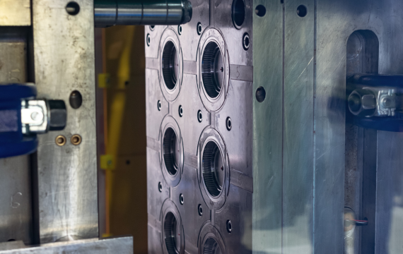
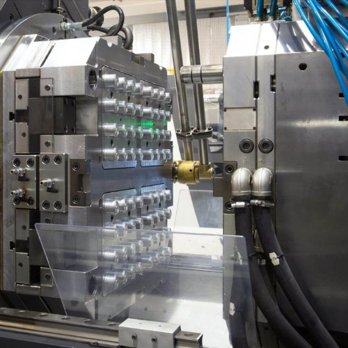
Plastic Injection Molding Mold Design and Construction Fundamentals

The standard tooling for Injection molding process is aluminum or steel mold. It features several elements, but can be divided into two halves, with each half fixed in the injection molding machinery. The rear half is capable of sliding to facilitate opening and closing of the mold along its parting line.
Injection Molding Tool Construction
The two primary injection mold components are mold cavity and mold core. The area between the cavity and core if you close the mold is the part cavity. This is where you load the molten raw material to construct the expected plastic part. In some instances, multi-cavity injection tooling is employed, where two tooling halves create various part cavities.
Mold Base
The mold cavity and core are each installed on the mold base that is then secured to the injection molding machine platens. The mold cavity is secured to a support plate found on the mold base front half. Similarly, mold core is fixed to the ejection mechanism found on the mold base rear half.
Mold Channels
Mold design features many channels that facilitate flow of molten plastic injection molding raw material into the part cavities.
Types of Molds for Plastic Injection Molding
There are several mold types for plastic parts fabrication employing injection molding process, which are categorized based on:
Feeding System
Here, the injection tooling is classified based on runner system, which constitutes a sequence of channels, consisting of a sprue, runners, and gate. There are two types of injection molds in this category:
- Hot runner injection mold
- Cold runner injection mold
Number of Cavities
This injection mold category is dependent on the plastic parts volume the molds can fabricate per cycle. The number of mold cavities dictate the amounts of parts constructed in every cycle and significantly influence the injection molding speed.
- Single cavity injection mold
- Multi cavity injection mold
- Family injection mold
Number of Plates
Injection tooling can also be classified using the number of plates in it. Mold plates form the whole mold cavity to facilitate successful injection molding process. The mold types in this class include:
- Two-plate injection mold
- Three-plate injection mold
- Stack injection mold
Steps of Plastic Injection Molding Process
Presuming that the mold is ready, there are 5 plastic injection molding steps that include:
Clamping
In clamping stage, the two mold metal plates (core and cavity) are thrusted against each other inside the injection molding equipment. This forms the cavity where you will load with melted plastic to develop the desired part.
Insufficient clamping pressure leads to flashing defects close to the parting line due to molten resin leakage because of high pressure. These defects diminish the plastic part quality and calls for physical trimming between runs to eliminate the overspill material.
Injection
Molten plastic injection starts after completion of the clamping operation. First, the pellet or granular plastics are melted within a heated container. Afterward, the molten material is delivered into the tooling cavity by an injection molding press.
The correct temperature leads to a molten plastic having sufficient viscosity to allow laminar flow in the injection step. Maintaining a high pressure makes sure that all spaces in the cavity is loaded with material whilst eliminating air bubbles. The clamp and injection pressure must also be balanced to avoid plastic leakage at the mold parting line.
Dwelling
This step involves holding the injected material under pressure over a varying time after achieving the desired fill of the whole injection mold. Holding stage of plastic injection molding process guarantees that all mold cavity spaces are filled whilst the tooling is cooling. This prevents formation of any sink marks in the finished product.
Cooling
Water oil flowing across the cooling channels help in the injection mold cooling. With time, the plastic material cools and cures properly into the required shape. The plastic part normally shrinks and adheres to the tooling cavity wall during the injection mold cooling step.
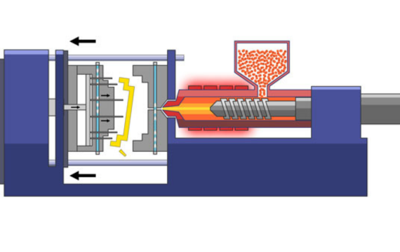
Ejection
After opening the clamping unit, an ejection system of the plastic injection molding unit thrusts powerfully the constructed part out. Cutters help in removing any overspill on the part’s surface to ensure a defect-free end product. You can recycle the gathered residue material to lower material costs.
Post-Processing Techniques in Plastic Injection Molding

Plastic parts can receive secondary processing after completing injection molding operation. Some of the popular post-processing methods to join components, add decorations, or eliminate surface flaws include:
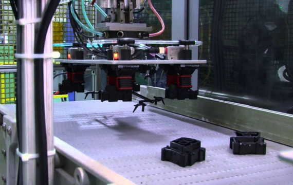
Part Assembly
Majority of injection-molded plastics products feature a virtually finished look following molding process. Nonetheless, at times you might need to join the parts in order to have a more detailed end product. The common injection molding post processing assembly methods include:
- Mechanical Fastening: Ensures easy disassembly of the joined injection-molded parts in the future. Bolts, rivets, nuts, and screws are the common mechanical fasteners used. Plastic parts needing recurrent disassembly feature threaded metallic inserts that enhance thread longevity.
- Adhesive Bonding: Uses adhesive materials to fuse two parts without modifying the plastics chemically.
- UV Bonding: This technique employs UV beams for curing or drying coating or adhesives. It develops permanent joints much faster, boosting fabrication quality and lowering rejection rates.
- Solvent Bonding: Utilizes a liquid substance that laminates and softens individual plastic sufficiently enough to fuse using a press. The two plastic molecules blend to create a permanent joint during the solvent evaporation process. This post-molding assembly method is works perfectly with thermoplastics.
- Ultrasonic Welding: Welds the molded parts employing high-frequency acoustic vibrations. The process does not require any extra material for bonding the parts.
Part Decoration
Plastic part decoration is necessary if you want to incorporate identifications, directions, or aesthetics. You can employ any of these conventional techniques for decorating injection-molded plastic parts:
- Inkjet Printing: Facilitates a non-contact, precise printing technique. Inkjet printing using an ink with intricate properties to enhance the print results.
- Laser Marking: Includes laser engraving and laser etching, laser marking technique gives quick alternative for plastic parts decoration. It results in high-resolution impacts on the injection-molded part minus requiring preceding surface preparation.
- Pad Printing: The method lifts 2D text or images onto 3D substances using silicone pad. It is suitable for round plastic parts because the silicone pad encases around them without deforming the texts or images.
Plastic Injection Molding Cost Considerations


There are several factors that determine plastic injection molding cost, making it complicated to calculate the overall production expenses. However, we are going to summarize the variable into the three key factors that influence the general injection molding cost per unit:
Material Cost
The weight needed and unit price of the material dictates the general injection molding material cost. The material weight needed is dependent on material density and part volume. Nevertheless, maximum wall thickness of plastic part can equally add to the weight. The plastic injection molding material weight necessary also encompasses the material that will fill the injection tooling channels.
Production Cost
The cycle time and hourly rate are the primary variable used in production cost calculation. The plastic injection molding machine size will influence the hourly rate directly. Typically, the equipment is referenced by the clamping force tonnage they give.
Projected part size and material injection pressure determine the clamping force needed. On this account larger injection-molded parts will need greater clamping force, meaning a costlier machine. Moreover, some materials that need high injection pressures might need greater tonnage equipment.
Resetting time, cooling time, and injection time make up the cycle time of injection molding equipment. You will realize lower production cost if you lessen any of the three times.
Reducing the part volume and its maximum wall thickness helps in lowering the injection time. Decreasing the wall thickness can also lower the cooling time, though many thermodynamic attributes of the material used also influence it. Lastly, the part size and machine size determine the resetting time, which in turn influence the cost of plastic injection molding machine price.
Tooling Cost
There are two primary components that influence injection tooling cost; mold base and cavities machining. The key determinant of the mold base cost is the plastic part size, as bigger parts need larger, costlier mold base.
Almost all the part geometry features affect the machining cost of injection mold cavities. The tooling cavity size (area and depth) is the major cost driver. Any additional elements, including unscrewing instruments, lifters, and side-cores, requiring extra machining will increase the expenses.
Parts quantity will also influence the plastic injection tooling cost. A high-quality mold that does not wear fast will be necessary for bulk production. Using robust mold materials leads to increased tooling base cost and machining time.
Injection Molding Advantages
The process allows for manufacturing of thousands of parts per hour. Plastic injection molding speed is dependent on mold size and complexity, ranging between 15 to 120 seconds per run.
One operator can manage the entire process since most operations are automated using robotics and machine. This is instrumental in lowering fabrication expenses as the operating costs are considerably minimized.
You can also use several polymer resins concurrently; for instance, it is possible to overmold PP onto TPE parts.
The process generates minimal post-fabrication residue in comparison to conventional manufacturing methods. Any waste or unused plastic can be recycled for later use.
Injection molding process allows for fabrication of plastic parts with any desired color applying compounding or masterbatches.
Being a repeatable operation, it facilitates continuous manufacturing of identical parts. This is beneficial in maintaining part reliability and high tolerances in mass production.
Injection molded parts often require minimal post-molding processes since they commonly possess good finished appearance on ejection.
The addition of plastic injection molding fillers helps in reducing the plastic volume, while boosting the strength of finished product.
Injection Molding Disadvantage
High Initial Costs
There is high capital requirement for plastic injection molding design and tooling. The process involves injection tooling designing and prototyping, which adds to the overall initial costs.
Part Design Restrictions
The plastic part design must take into account the fundamental injection molding guidelines and parameters. Effecting any design changes can be difficult since the molds are commonly constructed using steel or aluminum.
Costly Low Volume Runs
Small cycles of plastic parts are very expensive for injection molding operation. This is brought about by the tooling complexity and need to clear all preceding materials from the equipment prior to fabricating the next product.
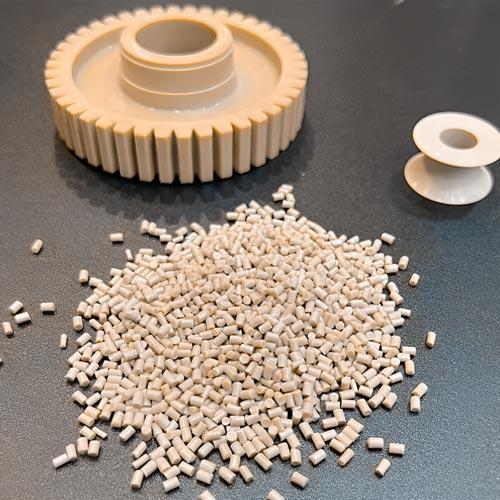
Plastic Injection Molding Materials
There are numerous plastic materials for injection molding process. You can use majority of polymers, consisting of all thermoplastics, certain elastomers, and certain thermosets. The raw form of these materials is normally fine powder or tiny pellets. Colorants might also be incorporated in the operation to give the finished part color.
Each material possesses distinct characteristics that will influence the function and strength of the end product. The characteristics determine the plastic injection molding parameters since every material has specific process parameters.
Here is a comparison table to help you with plastic injection molding material selection:
| Material name | Abbreviation | Description | Applications |
| Acetal | POM | Low/medium cost, naturally opaque white, rigid, strong, moisture resistant, chemical resistant, exceptional creep and fatigue resistance | Valves, plumbing components, slide guides, bearing, rotors, handles, cams, rollers, gears |
| Acrylic | PMMA | Low/medium cost, transparent, brittle, scratch resistant, rigid but brittle. | Trays, signs, light housings, shelves, reflectors, knobs, display stands, panels, lenses |
| Acrylonitrile Butadiene Styrene | ABS | Low/medium cost, naturally opaque, flexible, strong, chemical resistant, tight shrink tolerance, electroplating ability | Toys, housings, boxes, inhalers, motor vehicle (vents, consoles, trim, panels), gauges |
| Cellulose Acetate | CA | High cost, transparent, tough | Eyeglass frames, handles |
| Nylon (Polyamide 6) | PA6 | Medium/high cost, virtually opaque/white, high strength, chemical resistant, fatigue resistant, low creep and friction | Rollers, bearings, wheels, gears, bushings |
| Nylon (Polyamide 6/6) | PA6/6 | Medium/high cost, nearly opaque/white, low friction and creep, high strength, chemical resistant, fatigue resistant. | Zip ties, levers, small housings, handles |
| Nylon (Polyamide 11+12) | PA11+12 | Very high cost, high strength, virtually opaque/white, chemical resistant, low creep and friction, fatigue resistant | Eyeglass frames, Air filters, safety masks |
| Polycarbonate | PC | High cost, exceptionally tough, transparent, dimensionally stable, temperature resistant. | Safety shields and helmets, reflectors, containers, reflectors, bottles, light casings, housings, automotive (consoles, lenses, panels) |
| Polyester – Thermoplastic | PBT, PET | Medium/high cost, chemical resistant, heat resistant, rigid | Valves, electrical components (sensors, connectors), switches, cams, housings, automotive components (pumps, handles, filters), gears, bearings, rollers |
| Polyether Sulphone | PES | Very high cost, clear, exceptional chemical resistant | Valves |
| Polyether ether ketone | PEEK | Strong, abrasion resistant, low moisture absorption, thermally stable, chemical resistant | Seals, pump impellers, electrical connectors, aircraft parts |
| Polyetherimide | PEI | Transparent (amber in color), flame resistant, heat resistant | Covers, surgical tools, shields, electrical components (switches, boards, connectors) |
| Low Density Polyethylene | LDPE | Low cost, flexible and tough, natural waxy look, lightweight, outstanding chemical resistance | Containers, coverings, kitchenware, and housings |
| High Density Polyethylene | HDPE | Low cost, sturdy, outstanding chemical resistance, natural waxy look | Chair seats, containers, housing, and coverings |
| Polyphenylene Oxide | PPO | High cost, tough, low moisture absorption, dimensionally stable, flame resistant, heat resistant, electroplating ability | Housings, plumbing components, electrical components, automotive components (panels, housings) |
| Polyphenylene Sulphide | PPS | Very high cost, brown, exceedingly high strength, heat resistant | Shields, guides, bearings, switches, covers, guides, fuel system parts |
| Polypropylene | PP | Low cost, natural waxy appearance, lightweight, scratch resistant, excellent chemical resistance, heat resistant | Crates, housings, caps, handles, bottles, Automotive parts (bumpers, trim, covers) |
| General Purpose Polystyrene | GPPS | Transparent, fragile, low cost | Pens, cosmetics packaging |
| High Impact Polystyrene | HIPS | Low cost, dimensionally stable, tough, naturally translucent, good impact strength | Electronic casings, toys, food containers |
| Plasticized Polyvinyl Chloride | PVC | Low cost, transparent/opaque, tough, flame resistant | Shoe soles, toys, medical tubing, electrical insulation, housewares |
| Rigid Polyvinyl Chloride | UPVC | Flame resistant, low cost, flexible but tough, transparent/opaque | Outdoor applications (used in fittings, gutters and drains) |
| Styrene Acrylonitrile | SAN | Chemical resistant, low cost, transparent, heat resistant brittle but still, hydrolytically stable | Housewares, syringes, knobs |
| Thermoplastic Elastomer/Rubber | TPE/R | Flexible but tough, highly priced | Washers, bushings, seals, electrical components |
Troubleshooting Plastic Injection Molding Defects
Some plastic injection molding defects are inevitable, which can jeopardize the whole production process. Here are some plastic injection molding troubleshooting guides to the common defects:
| Defect | Causes | Remedies |
| Short shots
Refers to when you cannot fill the injection mold completely. |
1) Extremely low material temperature, die temperature, or injection speed and pressure
2) Non-uniform raw materials plasticization. 3) Inadequate raw material liquidity 4) Very small gate size or extremely thin part 5) Premature curing of molten polymer because of improper structural design 6) Poor exhaust |
1) Material: Utilize more fluid injection molding resin
2) Mold design a) Avoid retention issues by filling the thick wall first before thin wall filling. b) Correctly increase the runner size and gates number to minimize flow resistance and process ratio. c) Correctly set the size and position of exhaust port to prevent poor exhaust. 3) Machine a) Inspect for serious wearing of inner material cylinder wall and check valve. b) Confirm whether the feeding port contains material or is bridged. 4) Process a) Boost shear heat by raising the plastic injection speed and pressure. b) Increase the material injection quantity c) Raise the temperature of the material cylinder and injection tooling. |
| Air Traps
Describes when air is trapped within the injection mold cavity to form bubbles in the plastic part. |
Air unable to clear out from the vent, ram, or parting surface as the two melt fronts get in contact. | 1) Structural design: Make sure the wall thickness of the part is consistent
2) Mold design: a) Install a mold vent in the area filled last. b) Redesign the injection mold gate and runner system 3) Process a) Decrease the material injection speed in the final stage b) Raise the mold temperature |
| Brittleness
Scenario where the plastic part is easy to crack or break. |
1) Unsuitable curing conditions, or excessively recycled materials use.
2) Incorrect injection temperature setting 3) Improper runner and gate system settings. 4) Low melting mark strength |
1) Material
a) Set the correct drying conditions before starting the plastic injection molding process. b) Minimize recycled materials use and increase raw materials quantity c) Utilize high-strength plastic 2) Mold design: Enlarge the size of gate, branch runner and main injection mold runner system 3) Machine: Select a properly-designed screw to ensure uniform temperature distribution during plasticization 4) Process a) Lower the nozzle and material cylinder temperature b) Lower injection speed, screw speed, and back pressure c) Increase injection pressure and material temperature to enhance melting strength. |
| Burn Marks
These is blackening at the flow end due to untimely removal of the gas from the mold cavity. |
1) Delayed elimination of air out of the injection tool cavity
2) Material deterioration due to overcast screw speed, excessively high melt temperature, and poor runner system design.
|
1) Mold design
a) Incorporate an exhaust mechanism where there is high chance of gas generation b) Enlarge the size of injection mold runner system 2) Process a) Lower the plastic injection molding speed and pressure. b) Decrease barrel temperature c) Make sure that the heater and thermocouple are operating properly. |
| Flash
Describes excess plastic presence in the mold parting or ejector area. |
1) Inadequate clamping force
2) Defective injection mold 3) Incorrect plastic injection molding conditions 4) Improper exhaust system design |
1) Mold design
a) Ensure correct injection tooling design to ensure proper mold closing. b) Confirm the exhaust port size c) Celan the injection mold surface 2) Machine a) Lower the material injection speed, pressure and raise injection time. b) Lower the nozzle and barrel temperature |
| Delamination
Describes injection molding defect where there is layer by layer peeling of the surface of a finished part.
|
1) Blending incompatible plastic injection molding materials
2) Use of excess release agent during the plastic molding process 3) Inconsistent resin temperature 4) Excessive moisture 5) Sharp angles for the flow path and gate |
1) Material: avoid using incompatible or impure raw material blends
2) Mold design: Chamfer all gates and runners having sharp angles 3) Process: a) Raise the injection tool and barrel temperature b) Ensure proper material drying before molding operation c) Avoid utilizing too much release agent |
| Jetting
Formation of spray trace due to fast flow of molten polymer resin. |
1) Exceedingly small injection mold gate size facing part surface having broad cross-section.
2) Excessively fast filling speed |
Mold design
a) Enlarge size of the gate b) Enlarge the stop pin ahead of the mold gate c) Convert the side gate to lap gate |
| Flow Lines
Wavy plastic injection molding defects on the product surface due to slow molten material flow. |
1) Very low material and mold temperature
2) Exceedingly slow injection pressure and speed 3) Fast acceleration of filling flow because of plastic part structure.
|
1) Mold design
a) Enlarge the cold slug well within the flow channel b) Enlarge the size of injection mold gates and runners c) Shorten the main channel size or shift to hot runner system 2) Process a) Raise the resin injection speed b) Increase injection pressure c) Prolong pressure holding time Raise the injection tooling and material temperature |
| Streaks
Refer to injection molding defect where there is distribution of char, air, or water in the flow direction along the part surface. |
1) Very high moisture content within the injection molding raw material
2) Trapped air inside the material 3) Polymer degeneration due to inadequate injection volume, high barrel temperature, or contamination. |
Mold design
a) Check for correct exhaust positioning and improve the system if necessary b) Use suitable plastic injection molding machine and tooling c) Wash the previous materials from the barrel totally if switching resins d) Lower material injection speed/pressure, and melt temperature |
| Sink Marks
A common injection molding defect that often happen exhibit as depressions within the thicker plastic part segments |
1) Exceedingly low injection or holding pressure
2) Very short cooling or holding time 3) Excessively high melt or injection tool temperature 4) Improper plastic injection molding parts design |
1) Part Design
a) Apply corrugated surface in areas susceptible to dents b) Decrease the part wall thickness, aspect ratio, maintain adjoining wall thickness ratio at 1.5 to 2, while ensuring smooth transition. c) Remodel the thickness of counterbore and ribs, making them 40-80 percent of the part wall thickness 2) Process a) Raise the material injection pressure b) Enlarge the injection tooling gate size and position |
| Weld Lines
Refer to surface defect on injection-molded part brought about two material streams getting welded together |
1) Inconsistent wall thickness
2) Using multi-gate injection molding technique, presence of inserts, or holes |
1) Material: Increase the molten material fluidity
2) Mold Design a) Change the injection mold gate position b) Incorporate a venting opening 3) Process a) Raise the melt temperature b) Decrease release agent amount |
| Warpage
Troubleshooting this plastic injection molding defect is the most challenging.
|
1) Injection mold structure: Pouring, cooling, and ejection system
2) Plastic part structure: changes product wall thickness, having asymmetrical or curved geometry. Poor bosses and ribs column design 3) Production process: Incomplete cooling, and incorrect holding time and injection pressure. 4) Materials: injection molding resin lacks fillers and unsuitable shrinkage tolerance. |
Ensure balance cooling and heating within the mold.
Redesign the plastic size and shape in conformity with the resin properties |
Plastic Injection Molding Design Guide
The basic injection molding design considerations include the following:
Shrink Tolerance
Shrink tolerance is dependent primarily on plastic injection molding material selection and part design. Thus, there should be extreme care when choosing the right shrinkage and you should select the polymer grade before the injection mold design. Often, shrink tolerance ranges between 0.002 in./in. for stable materials like polycarbonate and ABS and 0.025 in./in. for unstable ones like TPE.
Maximum Wall Thickness
Wall thickness is critical since it can result in flaws like warp and sink. It is advisable to maintain an equal wall thickness across an injection-molded plastic part as this ensures even cooling and lessen flaws.
Reduce the maximum part wall thickness to decrease its volume and lessen cycle time (cooling time particularly). However, ensure that the wall is within the preferred thickness scopes for the chosen plastic injection molding material.
Corners
You should avoid sharp corners in any injection-molded part design. Sharp edges are the main cause of poor flow patterns, stress concentrations, increased injection tooling wear, and part failure.
Employ round corners to minimize fractures and stress concentrations, with the internal radius being at minimum the wall thickness. The corner design should always ensure exterior radius and minimum fillet radius are 150 and 50 percent of the wall thickness to guarantee even wall thickness.
Draft
Draft is necessary in all injection-molded parts to prevent warping during cooling and to ensure easy ejection from the plastic injection mold. Typically, the preferred injection molding draft angle ranges is 1-2 degrees, with extra 0.5 degrees on ribs.
Ribs/Gussets
Ribs should be incorporated for structural support, and not for expanding the wall thickness. They should have perpendicular orientation to the axis around which bending might happen. The injection molding rib thickness needs to be 50 to 60 percent of the wall you attach them to.
Make sure that the ribs height is not more than 3 times the part wall thickness and round the edges at the attachment point. Also employ not less than 0.25 degrees draft angle. The distance among multiple ribs should not be lower than twice the wall thickness to help lower injection tooling stress and cooling problems.
Bosses
Plastic injection molding bosses are incorporated to facilitate installation of self-tapping screws, guide pins, or threaded inserts into plastic parts. Refrain from stand-alone bosses if possible, rather attach them to ribs or walls.
- Bosses wall thickness must not be greater than 60 percent of the primary wall thickness.
- The base radius should be a minimum of 25 percent of the injection-molded part wall thickness.
- Support the bosses at the base using gussets or by ribs connecting them to adjoining walls.
- Isolate the bosses from the corner in order to eliminate sink marks and avoid thick areas.
- Avoid bosses completely on plastic parts having polished surfaces since they have sink marks or lead to ghosting on the surface.
Undercuts
Undercut prevent the injection tooling from opening, or the ejection of the part, or both. You can mold certain basic external undercuts through relocation of the parting line. However, in typical scenarios, you will need core lifters for internal undercuts and side-cores for external undercuts.
These extra features increase the injection tooling cost. Therefore, it is important to lessen the number of both internal and external undercuts in your part design. This can be achieved through redesigning of the plastic part.
Furthermore, it is essential to reduce the proportion of side-action directions. Extra side-action directions will restrict the amount of injection mold cavities.
Threads
If possible, injection molded parts featuring external threads should have perpendicular orientation to the parting direction. Threads plastic parts with parallel orientation to the parting line will need an unscrewing instrument, which significantly raises the injection tooling cost.
Gating
Material choice, part design, dimension and cosmetic specifications of the finished product will dictate the plastic injection mold gate type and design used. The gate is very important as it links the component to the injection mold runner system. Its design and position rely on the tooling design, injection molding material choice, and part geometry.
- Gate location should be far from high impact or stress regions.
- Gate designs ought to avoid auxiliary de-gating procedures as possible.
- Gate position should ensure efficient part filling, normally positioned in the thickest section.
- Multiple gates might be necessary in certain scenarios based on material selection, plastic part size and geometry.
Vents
Vents help in facilitating gases escape during the plastic injection molding operation. Absence of correct venting will lead to excess burn marks, short shots, injection pressure, splay and sink. There are numerous techniques of creating injection mold vents, but normally you do it by machining several shallow grooves at the mold parting line.
Weld/Knit Lines
These are the areas of convergence of two or additional flow fronts in the injection molded part. They often exhibit reduced strength compared to other sections. The injection molding part design should consider possible weld line positions and work on directing them off greater stress sections.